The IoT Journey: Introducing the Raspberry Pi Expansion Capabilities
In my previous post in this series, I introduced the Raspberry Pi3 and provided the steps necessary to build and configure it to run C# applications that were developed using Visual Studio on Windows. Obviously you need to know the basics in order to proceed to more IoT-relevant projects, so if you’re just getting started in the IoT world with the Raspberry Pi, please make sure you understand the concepts discussed in the first post.
In any IoT project, you’ll likely want some external sensor capability beyond what is provided by the Raspberry Pi itself. Examples of relevant sensors could be temperature and humidity sensors, barometric sensors, altimeter sensors, etc.. The list is limited only by your creativity and imagination.
The Raspberry Pi is very versatile in that it has expansion capabilities that allow us to both read data and write data using several common interface protocols.
In this post, I’ll discuss the Raspberry Pi’s expansion header and how to write data as well as read data from externally-connected “things”. Admittedly this post is going to enter into “uber geek” territory quickly, and if you’re the type of person that is easily intimidated by “raw electronics”, I’d suggest to you that even though it might look intimidating and complicated, working with electronic components and circuitry is not all that difficult and can be extremely rewarding, so please, read on and give it a go. You won’t be disappointed.
Step One – Obtaining the Necessary Components
When I was much younger, one of my favorite things to do was to grab my allowance savings and free battery card (ah, the memories) and run down to the local Radio Shack store to see what cool things I could afford. Although the stores have declined in popularity and capability somewhat, they have seen a resurgence due to the popularity of the “maker” community, and many stores do stock the components necessary to experiment with IoT. With that said, I have found that there are some very comprehensive kits available from Sunfounder that put all of the parts into a single kit. While there are many different kits available, I found that for my experimentation the following two kits were the most useful:
Super Starter Kit – This kit has pretty much everything you’ll want, although it is a little light on some of the more useful sensors.
Sensor Kit – This kit makes up for the missing sensors above and then some.
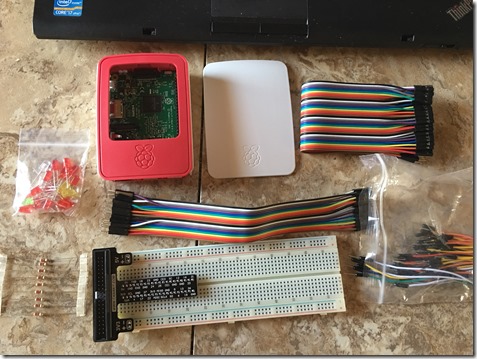
For the purposes of this post, you’ll need the following components (which are available in the Super Starter Kit):
- Breadboard – The breadboard allows you to place the components together in a circuit without the need to solder anything
- Raspberry Pi GPIO Expansion Board – This simply plugs into the breadboard and makes it easy to connect the components to the Pi
- Expansion Cable – The Raspberry Pi expansion header is 40 pins and the cable will connect the header on the Pi to the Breadboard
- 220 Ohm resistor – You’ll need this to ensure the circuit we build is properly configured
- Led – We will write code to turn the LED Light on and off
- Switch – We will use code to read the state of the switch and take action
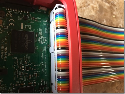
Once you have the components, you’ll want to connect everything to the expansion header in the Raspberry Pi (pay close attention to the pin layout – if you use the rainbow cables from the sunfounder kit mentioned above, you’ll want to connect it with the black wire (pin 1) closest to the end of the Raspberry Pi that contains the SD card. This can be confusing because the cable will fit in either direction, but it’s extremely important to connect the correct pin #s to the breadboard, otherwise you could find yourself applying the wrong signal or voltage to a sensor and at best destroying your sensor, and worst destroying the Pi….
Just make sure that the cable is correctly connected, and you’ll be OK.
Step Two – Prepare the Raspberry Pi
Once you’ve obtained the components and have plugged the expansion cable into the Pi, we need to make sure we have the appropriate development libraries installed in order to take advantage of the capabilities of the Pi.
The primary expansion capability on the Raspberry Pi is accessed through a series of General Purpose Input-Output (GPIO) pins. In short, the GPIO interface allows you to connect external devices directly to the Raspberry and then interact with that device. The “General Purpose” nature of this interface is exactly what makes the Raspberry Pi so popular with “makers”, and is what allows us to connect so many different devices to the Pi. This is the good news, the bad news, of course, is that because it is “General Purpose”, we need to actually write all of the code necessary to interact with the device. Fortunately, there are a number of very good libraries that already exist in the public domain that are designed to do exactly that.
Arguably the most popular and useful library is called Wiring Pi and is made available by Gordon Henderson. Gordon has made his library available using various methods and he is very good about reacting quickly to community feedback and requests for enhancement. This really does demonstrate the power of the Open Source community and is one reason that I’ve chosen to use open source tools for all of my IoT work.
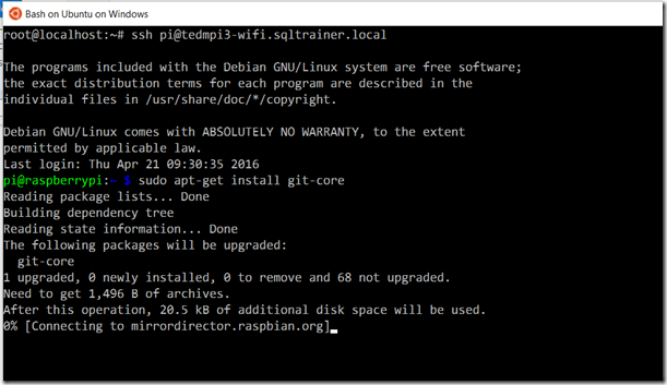
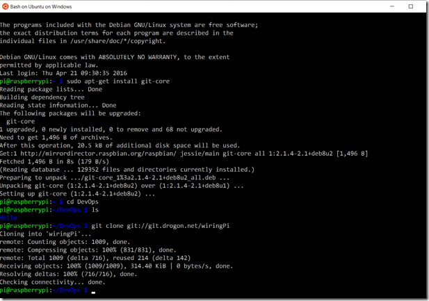
The easiest way to install the WiringPi library is to use git (git is a tool that allows you to interact directly with source code repositories) and install it directly on the Pi. To do this, you’ll first need to make sure you have the current version of the git command installed connect to your Pi via SSH (see the first post in this series for a refresher on how to do this) and then run the following command, sudo apt-get install git-core . (Git is usually preinstalled on the Raspbian image, but you want to install the latest version, which this command will do)
Once Git is installed, change directories to the DevOps folder that you created for the Hello application (created in the first post in this series) and then execute the following command: git clone git://git.drogon.net/wiringPi . This will install the git source code onto your Pi.
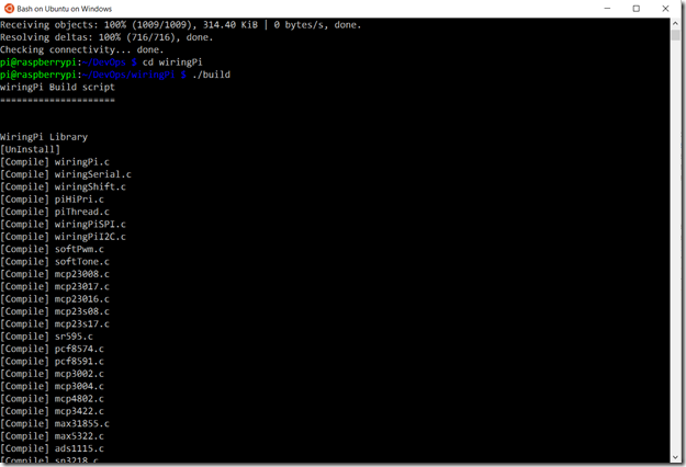
Once the source code is installed, you’ll need to compile the code that will be used by your applications. Fortunately Gordon makes this simple and has provided a build script to do all of this. Change directories to the wiringPi directory and execute the script by typing ./build to start the script.
You are now ready to start developing applications for the Pi that interact directly with the GPIO interface.
Step Three – Preparing your Development Environment
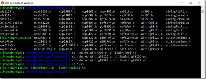
Now that your Pi is configured and ready to receive your IoT applications, you need to prepare your development environment to ensure that you can properly develop code that will run on the Pi and interact with the wiringPi library. This can get tricky, because we’re going to be developing our code in C# on windows, but the wiringPi library is written on C for Linux. The first step in preparing for this is to create shared libraries from the code we just complied on the Pi. For our purposes, there are 3 specific libraries that we will create. Change to the wiringPi folder (inside the wiringPi folder that you created) and execute the following commands to create the libraries:
- cc -shared wiringPi.o -o libwiringPi.so This command uses the compiler to create the basic library – this is the core library that we will use
- cc -shared wiringPiI2C.o -o libwiringPiI2C.so – This command creates the library specific to the I2C protocol – more on this in later posts
- cc -shared wiringPiSPI.o -o libwiringPiSPI.so – This command create the library specific to the SPI protocol – more on this in later posts
The next step in utilizing the wiringPi library is to build a C# wrapper that will encapsulate the functionality of the C libraries and allow you to use the C-on-Linux library as just another reference in your project. This is done in C# / Visual Studio by using an External Reference in a code file which tells the C# code where to “enter” the C code and what the specific interface looks like. As you might imagine, it can get fairly complex trying to read through the C source code to locate the routines that you want to use and then generate the appropriate wrapper. Fortunately for us, a gentleman by the name of Daniel Riches has taken the time to do just that and made his work available via open source. (yet another reason to love the open source community!)
In order to take advantage of the work Daniel has done, you’ll need to clone his git repository on your Windows development environment. You should already have git for windows installed, but if not, download it and install it, and then start the command line utility (which is PowerShell-based), switch to the root of the folder that you want to install the library in, and then issue the command git clone https://github.com/danriches/WiringPi.Net.git 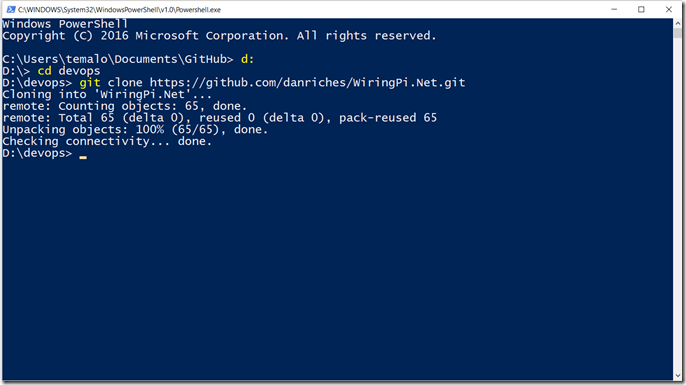
This will install the source code and test harness for the WiringPi.Net library, which you will use for all of the code that you develop moving forward.
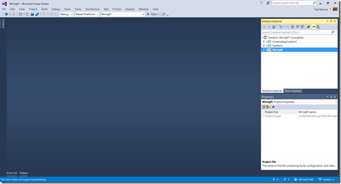
Once the library is installed, open Visual Studio and load the WiringPi.sln file that is included in the library. Right-click on the WiringPi project and then select Build.
This will create a .dll that you will reference in all of your other projects. Alternatively you can simply add the WiringPi code directly to each of your new solutions moving forward, but I personally find it easier to just add the .dll reference. (note, the default is to build the .dll in Debug mode, which is fine for our experiments, but if you are going to build production applications you’ll probably want to build it in Release mode)
Once your development environment is setup, you’re ready to develop the “Hello World” equivalent in the IoT world…
Step Four – Create a Simple IoT Application
In any IoT application, the basic components are a device or sensor that collects information and a repository for that information. For the purposes of this post, we will focus on the sensor aspect of IoT. In most cases, the sensor that you would work with in a real world application would collect data in an analog form, and then convert that data to a digital signal in order to communicate that to the host (in our case via the GPIO pins on the Raspberry Pi). The process of converting the analog information into a digital signal is a non-trivial process, so when you are beginning to learn to develop IoT applications, you want to start with the most basic and work your way up to the more complex tasks, learning along the way. One of the more basic tasks that you can perform is using code to light an LED light. (It may sound like a very simple and easy task, but even though it really is a basic task, there is a lot to be learned by performing this simple task).
For this step, you’ll need an LED (any color will do), a 220 ohm resistor (color code Red,Red,Black) and the wires necessary to connect them on the breadboard.
Wire the Breadboard
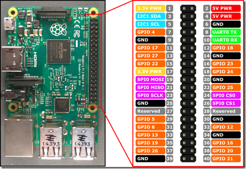
If you are using the same GPIO expansion header that I am from the Sunfounder kit, this will be relatively easy for you since the GPIO signals are marked on the header and it’s easy to understand what you are connecting to. If you aren’t using that, you will definitely want to pay attention to the Raspberry Pi pinout diagram below:
There is a fair amount of confusion around how the pins are referenced by both documentation and code, and this pinout diagram is one of the best available that shows the translation between the physical pin number, and the pin number as referenced by code. Due to the fact that hardware does occasionally change, most software libraries will reference the pin by function as opposed to location.
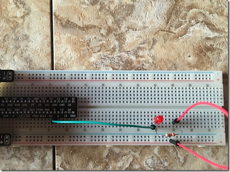
In our case, we are going to use GPIO 5 (physical pin 29) to drive the LED, and will use the 3.3v power (physical pins 1 or 17) as our power source. On the breadboard, plug the LED into an open space, and then connect the shorter leg (This is very important, the LED has 2 legs, one is longer than the other and must be installed in the correct direction to work correctly) to GPIO 5 and the longer leg to the resistor. Connect the other side of the resistor to the 3.3v supply. The circuit might look like this:
Note that I am using a header board that automatically connects the power to the edges of the breadboard, so I simply ran the 3.3v from that instead of to pin 1 or 17.
Once the circuit is complete, you can build a very simple application to turn the light on and off.
Developing the Hello World Application
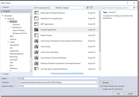
In Visual Studio, create a new C# Windows Console Application and name it PiLED.
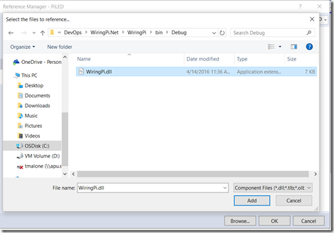
Once Visual Studio creates the project, right-click on the references node and select Add Reference. Select Browse, and browse to the location where you compiled the wiringPi library earlier. Select wiringPi.dll and then Add it to the project references.
This will ensure that the appropriate references are present for the code we’re about to write.
The basic process that we need to follow in order to instruct the Raspberry Pi to turn the LED on and off is:
- Initialize the GPIO Interface and tell it how we will reference the pins.
- Tell the GPIO Interface that we are planning to write to it
- Instruct the appropriate GPIO pin to turn LOW (which enables current to flow from the 3.3v power through the resistor and LED, thus lighting the LED)
- Pause (so that we can witness the LED in an ON state
- Instruct the appropriate GPIO pin to turn HIGH (and thus disable current flow through the LED)
- Wait for a key press
- Exit the program
The completed code (in the file program.cs in your project) looks like this:
using System;
using WiringPi;
namespace PiLED
{
class Program
{
// ENUM to represent various Pin Mode settings
public enum PinMode{
HIGH = 1,
LOW = 0,
READ = 0,
WRITE = 1
}
const int RedLedPin = 29; // LED is on GPIO 5 (Physical Pin 29)
//This is a console application with no GUI interface. Everything that happens will be in the shell
static void Main(string[] args)
{
Console.WriteLine("Initializing GPIO Interface"); // Tell the user that we are attempting to start the GPIO
if (Init.WiringPiSetupPhys() != -1) // The WiringPiSetup method is static and returns either true or false. Calling it in this fashion
//ensures that it initializes the GPIO interface and reports ready to work. We will use Physical Pin Numbers
{
GPIO.pinMode(RedLedPin, (int)PinMode.WRITE); // Set the mode of the GPIO Pin to WRITE (The method requires an integer, so CAST it)
GPIO.digitalWrite(RedLedPin, (int)PinMode.HIGH); //Ensure that the LED is OFF
Console.WriteLine("GPIO Initialization Complete");
Console.WriteLine("Press Any Key to Turn LED On");
Console.ReadKey(); // Pause and wait for user to press a key
GPIO.digitalWrite(RedLedPin, (int)PinMode.LOW); // Turn the LED On
Console.WriteLine("Led should be on");
Console.WriteLine("Press Any Key to turn the LED Off and Exit");
Console.ReadKey();
GPIO.digitalWrite(RedLedPin, (int)PinMode.HIGH); //Turn LED Off
}
else
{
Console.WriteLine("GPIO Init Failed!"); //If we reach this point, the GPIO Interface did not successfully initialize
}
}
}
}
Deploying the HelloWorld Application
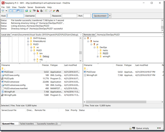
Once you have the code in Visual Studio, Compile it by using the Build option. Once the code is compiled, you will need to use a file transfer program to copy the .exe as well as the wiringPi.dll file to a directory on the Pi. (I use FileZilla, and created a new folder in the /DevOps folder called PiLED.
Once the file is copied you will need to execute the application on the Raspberry Pi.
Executing the HelloWorld Application
Connect to the Raspberry Pi and then change to the directory where you copied the files (in my case ~/DevOps/PiLED) and execute the application by using the mono command. In this case, since we are interfacing directly with the hardware, we must run the application as root by using the sudo command. The command is sudo mono PiLED.exe 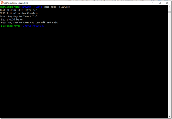
Once you start the application you will see the “Initializing” message. Press a key and the LED will turn on. Press another key and the LED will turn off and the program will exit.
Congratulations! You’ve just written your first application that will become the foundation for further IoT application development.
Future posts in this series will build on what you’ve created here and will demonstrate some of the other protocols as well as how to send data “to the cloud” to truly experience IoT development.
Comments
- Anonymous
May 16, 2016
Great series Ted - I'm having great fun and learning a huge amount. Just to say I've spotted a typo above which tripped me up: git clone git://git.drogon.net wiringPi should be git clone git://git.drogon.net/wiringPi.Cheers - Graham- Anonymous
May 16, 2016
Hi Graham -- Thanks for catching that. I've updated the article Cheers!
- Anonymous
- Anonymous
June 18, 2016
Just wanted to check your PinMode enum Ted. Is that the equivalent if WiringPi's GPIO.GPIOpinmode and GPIO.GPIOpinvalue?
