AX product configurator drives CAD and 3D printer.
More and more companies want to deliver configure to order scenarios at the cost of mass production - mass customization. This blog describes how the product configurator in Dynamics AX 2012 can drive programmable productions equipment like Cnc machines, 3D printers or robots.This post relates to the presentation on Convergence 2013 session DDAX19.
The scenario is
- Sales person settles all the configurable values in dialog with the customer utilizing the AX product configurator to guide the choices.
- From the configured product model, the values flows into the CAD (Computer Aided Design) 3D model which is updated based on the values.
- The updated CAD model is then persisted for 3D viewing and for CAM (Computer Aided Manufacturing) processing (generating code for the CNC- machine (e.g. a 3D printer) )
The values set during the configuration process are used to drive the dataflow towards the finished good.
The figure illustrates the workflow. The upper row represent systems and the lower row representing the created artifacts. The flow is driven from AX product configurator passing values to CAD/CAM systems and finally to the programmable manufacturing equipment here exemplified by a 3D printer. The 3D printer is a Cnc- machine and programmed the same way.
One important aspect is that you must ensure at the product model parameter and the CAD parameters are semantically aligned. The code assumes that you have loaded the CAD system with the corresponding cad model.
Figure 1 Flow through systems (top row) and generated artifacts (lower row)
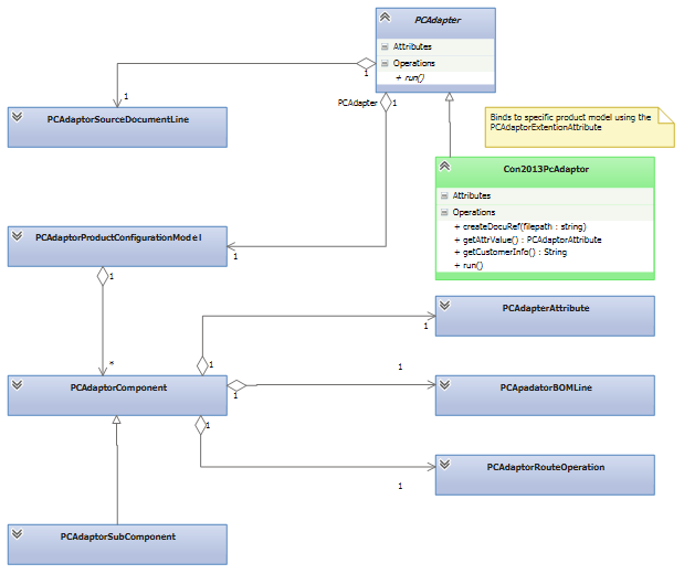
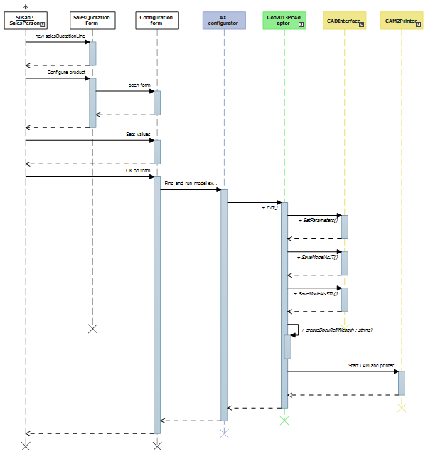
This workflow is implemented in X++ utilizing the Product Configurator API for extending configuration in AX 2012. Figure 2 illustrates the classes of the PC API. The PCAdapter hooks into the configuration workflow illustrated in Figure 3.
The customization is done by inheriting the PCAdapter class (Con2013PcAdapter is in green in diagrams) and bind the inherited class to a specific product model using the PCAdapterExtentionAttribute (see Figure 4).
The PcAdapter carries a reference to the SourceDocumentLine from which the customer information is fetched (see attached X++ code) and passes it on to the CAD model. Similar is the reference to the ProductConfigurationModel used to fetch values from the configuration. In the example the values of the parameter ‘speakerHeight’ is read (see attached X++ code) and passed on to the CAD model. The structure below PCAdaptorComponent also expose access to BOM Lines and RouteOperation, which X++ code could manipulate and update potentially based on calculations form the CAD system.
Figure 2 Product configurator extension framework
To support the workflow .Net wrappers for the CAD (in Figure 3 CADInterface) and CAM (in Figure 3 CAM2Printer) system are needed. The C# for this code is attached. The 3D printer drivers introduced by Windows 8.1 substitutes the CAM2Printer component.
Figure 3 Product configuration workflow with extension and CAD/CAM integration
The code below show the central parts of the X++ extension Class Con2013PcAdaper. Please note the model binding to the ‘Speaker Solution’ using the PCAdapterExtensionAttribute in the first line. The code using the InteropPermission instance is pluming code to handle security when calling external dll’s.
[PCAdaptorExtensionAttribute('Speaker solution')] // name of configuration model
public class Con2013PcAdapter extends PCAdaptor
{
}
public void run()
{
InteropPermission permission;
AxConfigCadInterface.LoudspeakerCad cadInterface; // Wrapper for CAD system
real size ;
str cName ;
str FilePath;
str ModelStore;
System.Exception exception;
System.Exception innerException;
try {
ModelStore = 'c:\\data\\modelStore\\';
permission = new InteropPermission(InteropKind::ClrInterop);
permission.assert();
size = this.getAttrValue('speakerHeight',
productConfigurationModel.getRootComponent()).parmIntegerValue();
cName = this.getCustomerInfo();
// SET CAD parameters
cadInterface = new AxConfigCadInterface.LoudspeakerCad();
cadInterface.SetParamenters(cName, real2double(size));
// CREATE A UNIQIUE filename
FilePath = strFmt('%1\\%2-%3',ModelStore ,cName,this.getUniqueID());
// EXPORT models in formats
cadInterface.SaveModelAsJT(FilePath);
cadInterface.SaveModelAsSTL(FilePath);
CodeAccessPermission::revertAssert();
// ADD viewer model URL
this.createDocuRef(FilePath);
// Send STL file to printer via CAM system
if (WinAPI::fileExists(strFmt('%1.stl',FilePath)))
WinAPI::shellExecute(strFmt('%1Cam2Printer.exe',ModelStore),
strFmt('\"%1\"',FilePath) );
}
catch
{
exception = CLRInterop::getLastException();
innerException = exception.get_InnerException();
info(strFmt('%1', innerException.get_Message()));
}
Figure 4 Con2013PcAdapter class definition and run() method in X++.
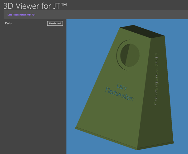
With the viewer model attached to the quotation line (Figure 4 code: this.createDocuRef(FilePath)), an extra menu entry “3D viewer” is introduced on the SalesQuotationTable form using a few lines of code (see code in attachment). The code on the menu entry opens the 3D model in the default 3D JT model viewer installed on your windows installation. Windows Store provides the free 3D viewer for JT files running Window 8. The configured model is shown in Figure 5 below.
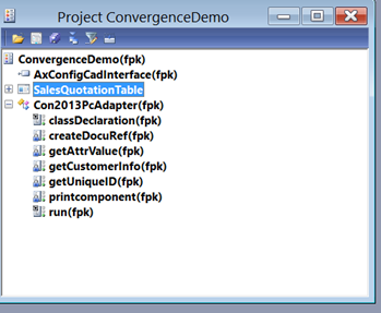
See the code changes in the attached X++ project.
Figure 5 Window 8 3D viewer for JT
How to install
Preconditions: AX 6.2 R2 installed and Visual Studio 2012
Install Autodesk inventor 2013 or 2014 from autodesk.com.
Autodesk DeveloperTools.msi (https://usa.autodesk.com/adsk/servlet/index?siteID=123112&id=1079044)
Install JT 3D Viewer from Microsoft Store on the Windows 8 (Only window 8 win32).
The CAM slicing and printer communication depends on the your 3D printer hardware. For the demo we used Slic3r for slicing and Pronterface for communication to the printer. With Windows 8.1 new 3D printer drivers will support this. See https://microsoft.com/3d
Download code.
The zip file constains:
- · Ax X++ code on in the Convergence2013PcCad3dPrinter.xpo file
- · C# autodesk wrapper
- · CAM2Printer code
Open AxConfigCadInterface.sln in visual studio 2012
- · Precondition: Autodesk developer tools (SDK). Update reference in project AxConfigCadInterface to Autodesk.Inventor.interop.dll which is a part of Autodesk (SDK).
- · Compile AxConfigCadInterface.sln. For simplicity the CAD interface in designed for the demo speaker model only.
- · Copy AxConfigCadInterface.dll and Autodesk.Inventor.interop.dll to AX client bin directory.
Import Convergence2013PcCad3dPrinter.xpo into AX developer environment and compile it.
Figure 6 X++ demo code
How to run
- · Open the CAD model in Inventor (both 2013 and 2014 works). Use CAD model speakerModel.ipt
- · From the Sales Quotation line configure a speaker in AX. When you press OK on the configuration form the CAD&CAM integration code is executed.
- · From the Sales Quotation line open the 3d Viewer which will visualize the configured 3D model.
I hope you find this interesting and useful for starts building integration scenarios driven by AX product configurator.


