DrawingGroup.ClipGeometry Propriété
Important
Certaines informations portent sur la préversion du produit qui est susceptible d’être en grande partie modifiée avant sa publication. Microsoft exclut toute garantie, expresse ou implicite, concernant les informations fournies ici.
Obtient ou définit la zone de découpage de ce DrawingGroup.
public:
 property System::Windows::Media::Geometry ^ ClipGeometry { System::Windows::Media::Geometry ^ get(); void set(System::Windows::Media::Geometry ^ value); };
public System.Windows.Media.Geometry ClipGeometry { get; set; }member this.ClipGeometry : System.Windows.Media.Geometry with get, setPublic Property ClipGeometry As GeometryGeometry qui est utilisée pour découper ce DrawingGroup. La valeur par défaut est null.
Cet exemple montre comment définir une région de clip pour un Drawing.
Utilisez un DrawingGroup élément pour définir un clip pour un Drawing. La DrawingGroup classe est le seul type d’objet Drawing qui vous permet de définir votre propre région de clip.
Utilisez un Geometry élément pour décrire le clip et l’appliquer à la ClipGeometry propriété de l’objet DrawingGroup .
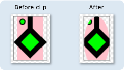
L’illustration montre le DrawingGroup clip avant et après l’application du clip elliptique.

L’exemple suivant utilise un DrawingGroup pour appliquer un ClipGeometry à plusieurs GeometryDrawing objets.
using System;
using System.Windows;
using System.Windows.Controls;
using System.Windows.Media;
using System.Windows.Media.Animation;
using System.Windows.Shapes;

namespace SDKSample
{
    /// <summary>
    /// Shows how to define a clip region for a DrawingGroup.
    /// </summary>
    public class ClipExample : Page
    {
        public ClipExample()
        {

            //
            // Create several GeometryDrawing objects.
            //

            // Create a rectangle.
            GeometryDrawing drawing1 = new GeometryDrawing(
                Brushes.Pink,
                null,
                new RectangleGeometry(new Rect(0,0,50,85))
                );

            //
            // Create a polygon.
            //
            PathFigure pLineFigure = new PathFigure();
            pLineFigure.StartPoint = new Point(25, 25);
            PolyLineSegment pLineSegment = new PolyLineSegment();
            pLineSegment.Points.Add(new Point(0, 50));
            pLineSegment.Points.Add(new Point(25, 75));
            pLineSegment.Points.Add(new Point(50, 50));
            pLineSegment.Points.Add(new Point(25, 25));
            pLineSegment.Points.Add(new Point(25, 0));
            pLineFigure.Segments.Add(pLineSegment);
            PathGeometry pGeometry = new PathGeometry();
            pGeometry.Figures.Add(pLineFigure);

            GeometryDrawing drawing2 = new GeometryDrawing(
                    Brushes.Lime,
                    new Pen(Brushes.Black, 10),
                    pGeometry
                );

            //
            // Create a circle.
            //
            GeometryDrawing drawing3 = new GeometryDrawing(
                    Brushes.Lime,
                    new Pen(Brushes.Black, 2),
                    new EllipseGeometry(new Point(10, 10), 5, 5)
                );

            // Create the DrawingGroup and add the
            // geometry drawings.
            DrawingGroup aDrawingGroup = new DrawingGroup();
            aDrawingGroup.Children.Add(drawing1);
            aDrawingGroup.Children.Add(drawing2);
            aDrawingGroup.Children.Add(drawing3);

            //
            // Create an EllipseGeometry and use it to
            // clip the DrawingGroup.
            //
            EllipseGeometry clipGeometry =
                new EllipseGeometry(new Point(25,50), 25, 50);
            aDrawingGroup.ClipGeometry = clipGeometry;

            // Use an Image control and a DrawingImage to
            // display the drawing.
            DrawingImage aDrawingImage = new DrawingImage(aDrawingGroup);

            // Freeze the DrawingImage for performance benefits.
            aDrawingImage.Freeze();

            Image anImage = new Image();
            anImage.Source = aDrawingImage;
            anImage.Stretch = Stretch.None;
            anImage.HorizontalAlignment = HorizontalAlignment.Left;

            // Create a border around the images and add it to the
            // page.
            Border imageBorder = new Border();
            imageBorder.BorderBrush = Brushes.Gray;
            imageBorder.BorderThickness = new Thickness(1);
            imageBorder.VerticalAlignment = VerticalAlignment.Top;
            imageBorder.HorizontalAlignment = HorizontalAlignment.Left;
            imageBorder.Margin = new Thickness(20);
            imageBorder.Child = anImage;

            this.Background = Brushes.White;
            this.Margin = new Thickness(20);
            this.Content = imageBorder;
        }
    }
}
<Page
  xmlns="http://schemas.microsoft.com/winfx/2006/xaml/presentation"
  xmlns:x="http://schemas.microsoft.com/winfx/2006/xaml"
  xmlns:PresentationOptions="http://schemas.microsoft.com/winfx/2006/xaml/presentation/options"
  xmlns:mc="http://schemas.openxmlformats.org/markup-compatibility/2006"
  mc:Ignorable="PresentationOptions"
  Background="White" Margin="20">

  <Border BorderBrush="Gray" BorderThickness="1"
    HorizontalAlignment="Left" VerticalAlignment="Top"
    Margin="20">
    <Image Stretch="None" HorizontalAlignment="Left">
      <Image.Source>
        <DrawingImage PresentationOptions:Freeze="True">
          <DrawingImage.Drawing>

            <!-- A DrawingGeometry with an elliptical clip region. -->
            <DrawingGroup>
              <GeometryDrawing Brush="Pink">
                <GeometryDrawing.Geometry>
                  <RectangleGeometry Rect="0,0,50,85" />
                </GeometryDrawing.Geometry>
              </GeometryDrawing>
              <GeometryDrawing Brush="Lime"
                Geometry="M 25,25 L 0,50 25,75 50,50 25,25 25,0">
                <GeometryDrawing.Pen>
                  <Pen Thickness="10" Brush="Black" />
                </GeometryDrawing.Pen>
              </GeometryDrawing>
              <GeometryDrawing Brush="Lime">
                <GeometryDrawing.Geometry>
                  <EllipseGeometry Center="10,10" RadiusX="5" RadiusY="5" />
                </GeometryDrawing.Geometry>
                <GeometryDrawing.Pen>
                  <Pen Thickness="2" Brush="Black" />
                </GeometryDrawing.Pen>
              </GeometryDrawing>

              <DrawingGroup.ClipGeometry>
                <EllipseGeometry Center="25,50" RadiusX="25" RadiusY="50" />
              </DrawingGroup.ClipGeometry>
            </DrawingGroup>
          </DrawingImage.Drawing>
        </DrawingImage>
      </Image.Source>
    </Image>
  </Border>


</Page>
Les dessins en dehors de la géométrie sont coupés à partir du DrawingGroup moment où il est rendu. La géométrie n’a pas besoin d’être rectangulaire ; par exemple, vous pouvez utiliser un EllipseGeometry clip pour une forme elliptique.
DrawingGroup les opérations sont appliquées dans l’ordre suivant :
| Champ d’identificateur | ClipGeometryProperty |
Propriétés de métadonnées définies sur true |
Aucun |